Aircraft Design Project
Discus 2C Glider — Nose-Cone Design & Integration
A multidisciplinary team project to design and develop a 1.2 m hand-launched glider based on the Schempp-Hirth Discus 2C. My individual responsibility was the nose cone: aerodynamic profile research, geometry development in CAD and coordination with the fuselage interface.
- My role
- Nose-Cone Research, Design & Integration
- Project
- Collaborative Glider Design
- Tools
- Autodesk Inventor
- Methods
- Aerodynamic Research · Profile Comparison · Engineering Drawings · Interface Coordination
- Year
- 2026
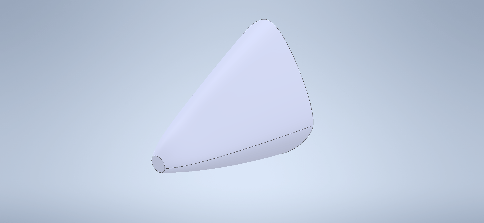
Project Brief
The wider team was tasked with developing a lightweight, hand-launched aircraft with a 1.2 m wingspan and a target whole-glider mass of 225 g. The Schempp-Hirth Discus 2C provided the reference geometry. Within that shared design, I was responsible for the nose cone, where airflow first meets the fuselage.
The engineering problem
The nose needed a justified aerodynamic profile, dimensions appropriate to the model and a practical route to manufacture in lightweight material. Its rear section also had to match the fuselage: the aircraft’s external contour depended on both components meeting continuously.
My contribution
I compared profiles, researched airflow and drag, developed the Inventor model and orthographic drawing, and coordinated the rear cross-section with the fuselage team.
The design direction
A Discus-inspired combination of elliptical and ogive characteristics, chosen for smooth curvature, gradual tapering and a continuous transition into the fuselage.
Choosing the reference aircraft
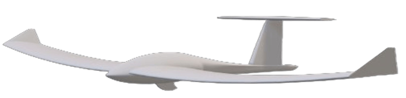
I reviewed the Carioca 2000 model glider alongside the full-scale Discus 2C. The Carioca provided a useful small-model reference, while the Discus offered a more refined, smoothly contoured nose. The team selected the Discus as the geometric reference, and I examined its rounded leading contour and gradual taper for adaptation to the model.
Design Constraints
The nose could not be designed in isolation. Its shape, material and rear interface had to support the wider glider brief.
1.2 m wingspan
The model wingspan set the geometric scale used as the starting point for the nose design.
225 g target mass
This was the whole-glider design target, not a nose-cone mass or a measured final aircraft mass. It supported the choice of a lightweight material.
A continuous interface
The rear cross-sectional shape and area needed agreement with the fuselage team. A locally smooth nose would be insufficient if the joint introduced a geometric discontinuity.
A shape that could be made
The proposed route was shaping and sanding balsa to the CAD profile. The contour needed to balance aerodynamic intent with this practical manufacturing approach.
Aerodynamic Research
My research connected the nose profile to the way airflow develops over the fuselage. For a small hand-launched glider, the design discussion centred on low-speed flow, drag and the practical quality of the finished surface.
Interference at component junctions
The research examined how airflow interacts at airframe junctions. For the nose, this reinforced the need to agree a continuous external interface with the fuselage team rather than optimise the part in isolation.
From research to selection
The comparison therefore considered curvature, taper, surface finish, shaping practicality and the fuselage junction together. These criteria connected the aerodynamic discussion to choices I could make in CAD and in the manufacturing proposal.
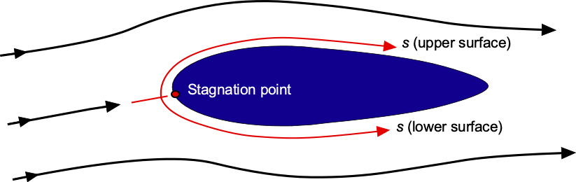
Pressure and the leading contour
I examined the stagnation region at the front of the nose, where the oncoming flow slows, and the acceleration of air around its curved surface. This made the leading contour and the transition into the fuselage central to the profile comparison.
Design implication: favour continuous curvature and gradual changes in the external profile.
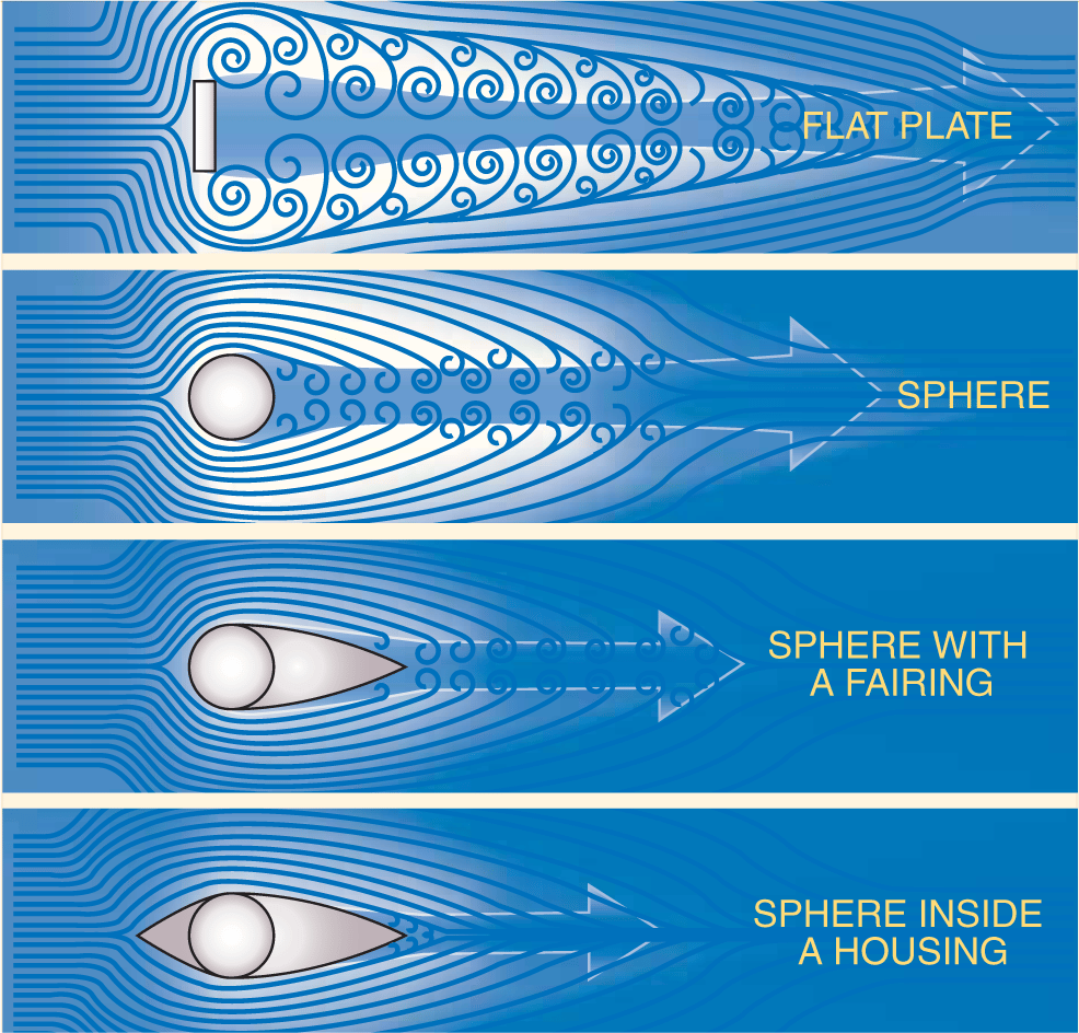
Form drag and separation
The assignment considers how separation leaves a wake behind a body and contributes to form drag. I compared the effects of blunt and streamlined shapes in the reference material, then used the same question to assess the candidate noses: how abruptly does the contour ask the flow to change direction?
Design implication: a gradual taper supported the elliptical–ogive direction.
Boundary layers and surface finish
I researched laminar and turbulent flow and the effect of roughness on skin-friction drag. Geometry alone was not the whole design problem: the proposed balsa surface also needed shaping, sanding and consideration of a filler or resin finish.
Design implication: consider the achievable surface alongside the CAD contour.
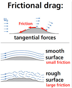
Research method and scope
The work used aerodynamic literature and reference diagrams to develop a qualitative design rationale. Laminar flow, attachment and reduced separation were design objectives; no pressure field, boundary-layer measurements or CFD results were produced for the individual nose cone.
The assignment discusses low-Reynolds-number operation without calculating a Reynolds number. Geometric scaling supplied a dimensional starting point; aerodynamic similarity was not established by the scale factor alone.
Profile Comparison
I evaluated conical, elliptical and ogive profiles qualitatively. The decision balanced the smoothness of the contour against the practicality of forming a small balsa component.
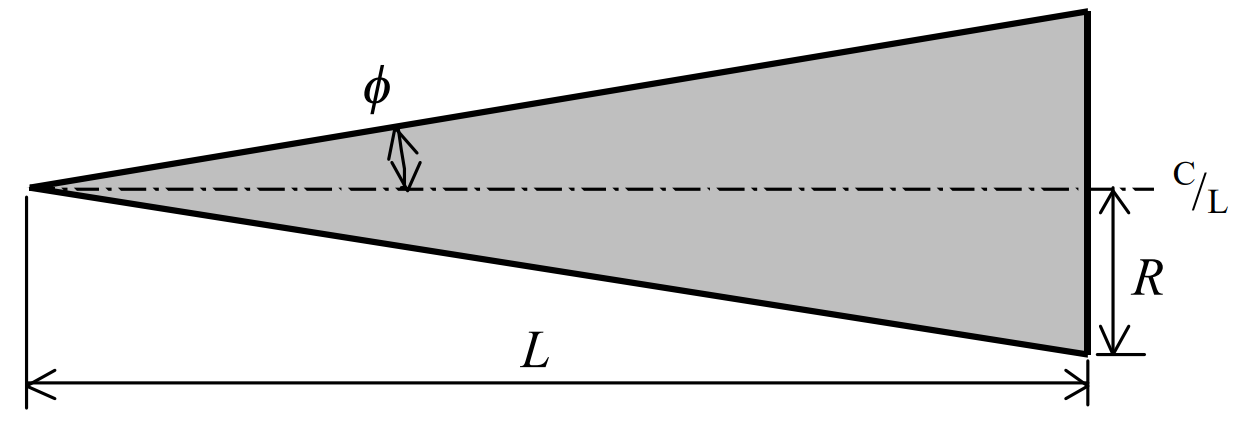
Conical
Straight sides made the conical profile simple to form. Its abrupt geometry was less suited to the smooth contour sought for this low-speed glider.
Simple to form; not the selected direction.
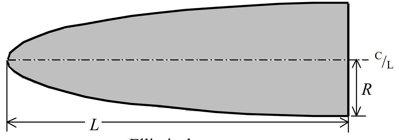
Elliptical
Continuous curvature supported gradual changes in flow direction and pressure. Reproducing that contour would require careful shaping and sanding.
Continuous curvature informed the design.
Ogive
An arc-based contour offered a smoother transition than the conical candidate, balancing aerodynamic intent with practical shaping.
Curved taper with practical shaping considerations.
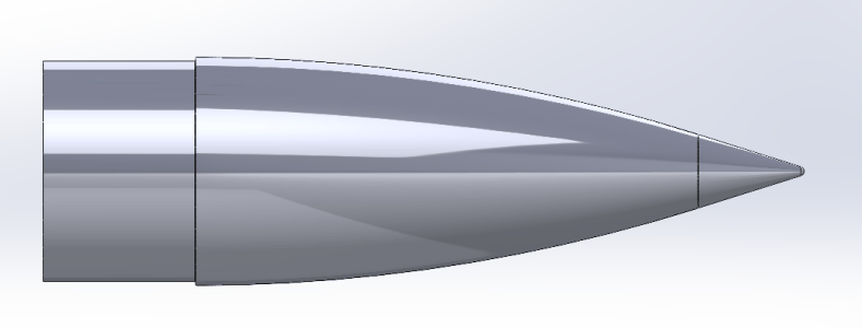
Selected geometry
Elliptical–ogive nose profile
The selected elliptical–ogive nose geometry combined smooth curvature and gradual tapering with a rear section coordinated to the fuselage. Selection was based on qualitative aerodynamic research and practical integration constraints.
Research became a geometric design direction.
Comparison methodology
The source discusses low-Reynolds-number operation, but does not provide a Reynolds-number calculation or a quantified comparison of candidate drag. The comparisons above describe the reasoning recorded in the portfolio, not experimentally established rankings.
Geometric scaling from a full-size sailplane gives a dimensional starting point. It does not, by itself, demonstrate equivalent aerodynamic behaviour at model scale.
CAD Development
I developed the nose cone in Autodesk Inventor, scaling and shaping the geometry and documenting it in an orthographic engineering drawing.
0.08 scale factor
The portfolio uses the 1.2 m model wingspan divided by a 15 m reference wingspan to establish the geometric scale.
38 mm nominal nose length
With no official nose dimension available, I assumed a nose length of 7% of the scaled fuselage length. The resulting 37.968 mm was rounded to 38 mm.
From profile to geometry
The selected direction combined elliptical and ogive characteristics. I carried the intended smooth curvature into a scaled component while coordinating the rear section with the fuselage team.
Model the component in Inventor
I developed the scaled nose geometry in Autodesk Inventor. The model defines the external contour and rear face; the orthographic drawing below then communicates the geometry through multiple views and dimensions.
The CAD is the output of the profile research and interface decisions.
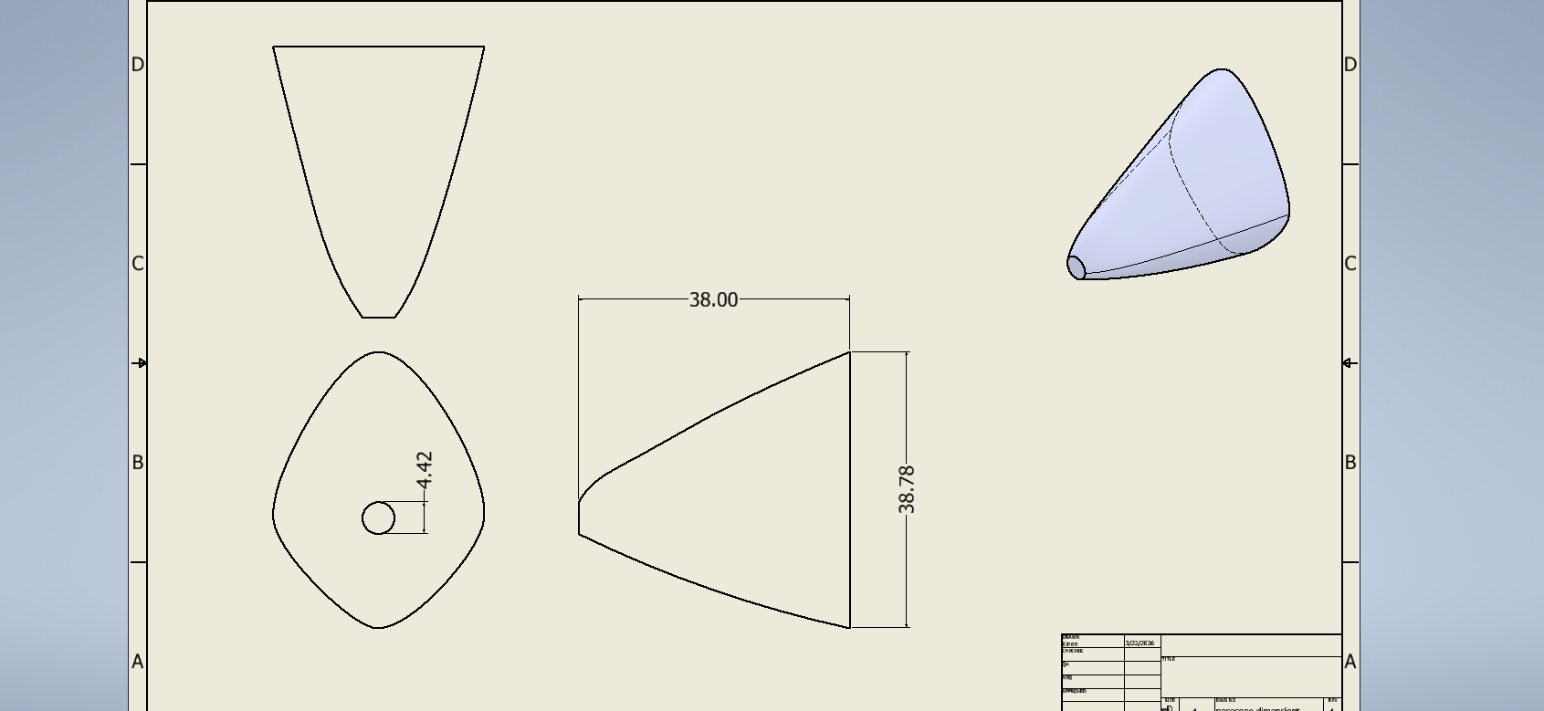
Dimensional development
Scale factor = 1.2 m ÷ 15 m = 0.08
Scaled fuselage length = 6.78 m × 0.08 = 0.5424 m = 542.4 mm
Assumed nose length = 0.07 × 542.4 mm = 37.968 mm ≈ 38 mm
The 7% proportion is an explicit design assumption. The drawing communicates the chosen geometry; the source does not provide a tolerance analysis or a sequence of separate CAD revisions.
Fuselage Integration
The rear face of the nose was both a physical joint and a transition in the external aerodynamic surface. I coordinated its cross-sectional shape and area with the fuselage team. Matching these features mattered because the intended smooth contour depended on the two independently developed parts meeting correctly.
Define the individual part
The nose model establishes the contour and rear interface. The manufacturing proposal uses a flat rear face for wood-adhesive bonding; a locating peg or dowel is described as an option to assist alignment.
The nose cone was my design responsibility.
Place it in the team assembly
The wider assembly provides context for the interface. Early dimensional agreement reduced integration risk, while shared files and team meetings kept the component work coordinated.
The complete aircraft was a collaborative output.
Manufacture and team coordination
Balsa was selected for low density, workability and the ability to shape and sand the contour. A filler or resin coating was proposed for durability. More complex composite routes were not prioritised because of cost, manufacturing complexity and the expected low loads of the model.
The report proposes adhesive bonding and an optional locating feature; it does not include a joint-strength test. These details describe the intended manufacturing route, not evidence that I manufactured the complete glider.
The documented coordination measures include Microsoft Teams and cloud file storage, regular meetings, clear responsibilities, internal checkpoints and early agreement on dimensions.
Repair by sanding or material replacement and eventual repurposing were considered at the concept level. The portfolio does not quantify lifecycle impacts.
Outcome
My output connected a qualitative aerodynamic comparison to a defined CAD component, an engineering drawing and an agreed fuselage interface.
Individual output
Profile evaluation, a justified design direction, dimensional scaling, the Inventor nose-cone model and an orthographic drawing.
Contribution to the aircraft
A component developed around the wider fuselage geometry and a practical proposed manufacturing route. The team designed and tested the complete glider.
Evidence boundary
The individual portfolio supports the design rationale and CAD output. It does not establish a measured drag reduction, CFD validation or individual physical-test results.
Reflection
This work developed my ability to turn aerodynamic research into CAD decisions. Comparing alternatives gave me a reason for the contour before I began refining the model.
Research into geometry
Comparing conical, elliptical and ogive profiles gave me a basis for the geometry before modelling it. In Inventor, that research had to become a defined contour and dimensions that another team member could interpret.
Engineering across an interface
The fuselage team controlled the adjoining geometry, so I had to resolve the rear section through discussion rather than treating it as an independent design choice. This connected CAD development with the practical task of making components fit.
Making assumptions explicit
The 7% sizing assumption and the proposed balsa process show where judgement entered the design. Keeping those distinct from verified dimensions and test results makes the work easier to review and develop.